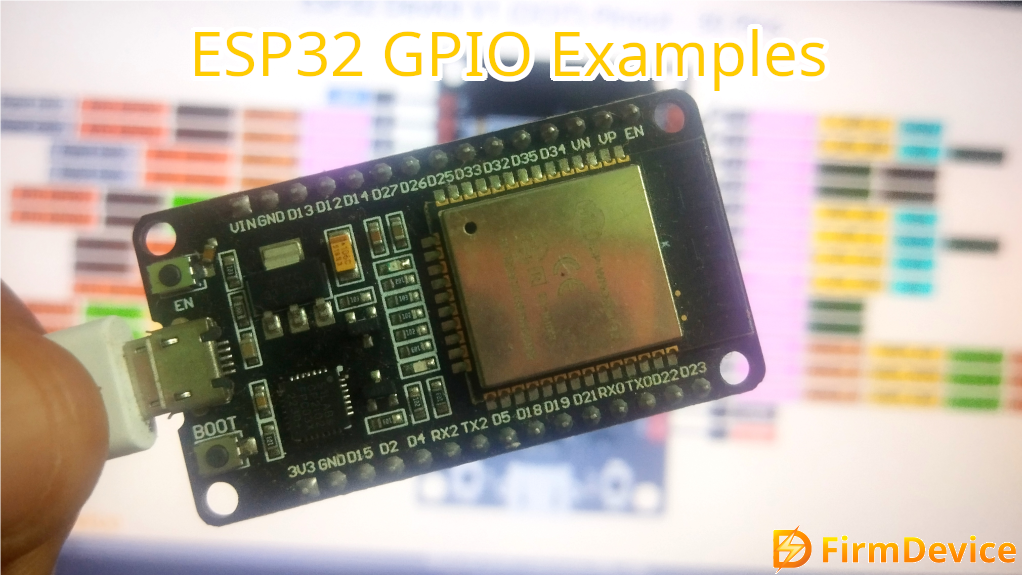
Introduction to ESP32 Dev Board
ESP32 Development board has become very popular among Electronics Engineers, Designers and electronic makers, due to its powerful capabilities like Wi-Fi, Bluetooth, Internal Sensors and custom GPIO’s etc., If you are building affordable IoT device, Sensor node or a smart device with internet connectivity then ESP32 is the right choice.
ESP32 – Short Into
ESP32 is a low power System on Chip Microcontroller from Espressif Systems and it is very cheap. It is said to be the successor to the popular ESP8266 (previous chip from espressif) with more features.
ESP32 chip have the following core components.
- 32 bit Dual core Tensilica Xtensa LX6 Processor (up to 240 MHz operating frequency)
- Wi-Fi (802.11 b/g/n)
- Bluetooth 4.2 (Classic and BLE)
- Lot (34 – Varies depends on Dev boards) GPIOs and peripherals.
- Built in Flash and SRAM memory.
- Low power modes for Battery powered operations.
ESP32 Dev Board
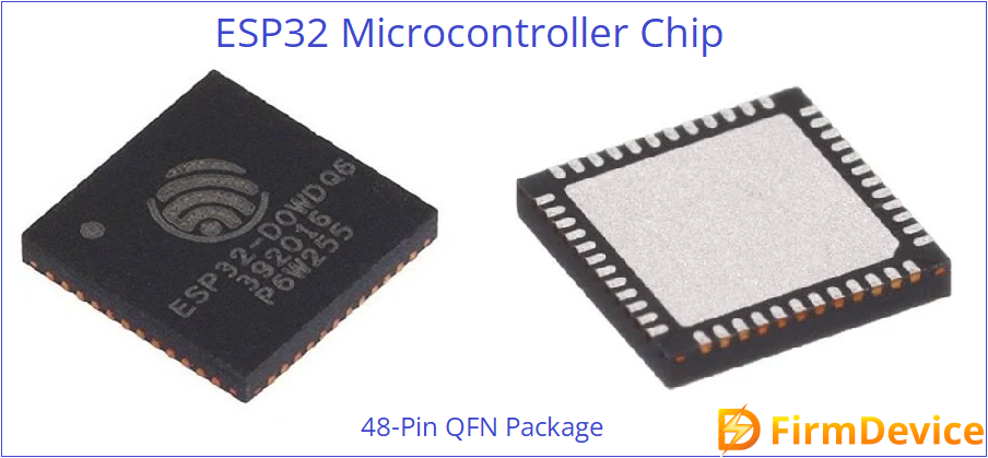
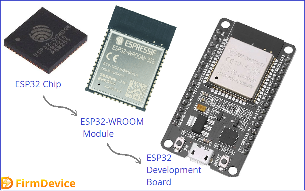
ESP32 Microcontroller comes in 48 Pins QFN package so that we need easy to handle development board. ESP32-WROOM is the kind of module that contains ESP32 Chip, Flash memory chip and then Antenna for WiFi / Bluetooth in a single compact PCB package with metal closure. ESP32 Dev board contains ESP32 Wroom module, USB to UART bridge, Power supply regulators, LED, Buttons for BOOT and EN (enable), External pins some other components. For testing and development we use this kind of boards.
We can directly use this ESP Dev boards without need for custom PCBs.
Key features of ESP32 Development Board
| Feature | Specification |
|---|---|
| Processor | Dual-core Tensilica LX6 @ 240MHz |
| Memory | Up to 520KB SRAM, 4MB Flash (varies) |
| Connectivity | Wi-Fi, Bluetooth (Classic & BLE) |
| GPIO Pins | 30–38 (varies by board) |
| Analog Inputs | 12-bit ADC (18 channels) |
| Digital I/O | PWM, I2C, SPI, UART |
| Timers | Multiple 64-bit timers |
| Other Interfaces | CAN, I2S, IR, Touch Sensor, DAC |
| Operating Voltage | 3.3V (with onboard 5V to 3.3V regulator) |
| Power Modes | Active, Light Sleep, Deep Sleep, Hibernation |
Popular ESP32 Dev Boards in the Market
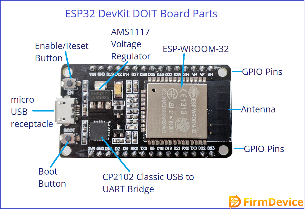
ESP32 DevKit V1
This is the Most widely used board in ESP32 series. It is available in 30-pin and 38-pin versions. Includes micro USB port, onboard voltage regulator, and reset/boot buttons.
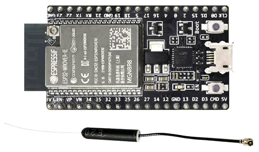
ESP32 WROVER
This board comes with additional PSRAM (up to 8MB). It is Ideal for applications with high memory needs like camera, audio processing. Comes with external UFL connector antenna.
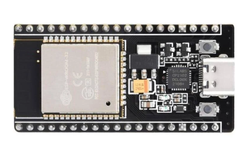
NodeMCU-32S
This Board Comes with ESP32-32S module. NodeMCU-32S is the upgrade version of NodeMCU ESP8266. It Offers USB programming and more accessible pin layout.
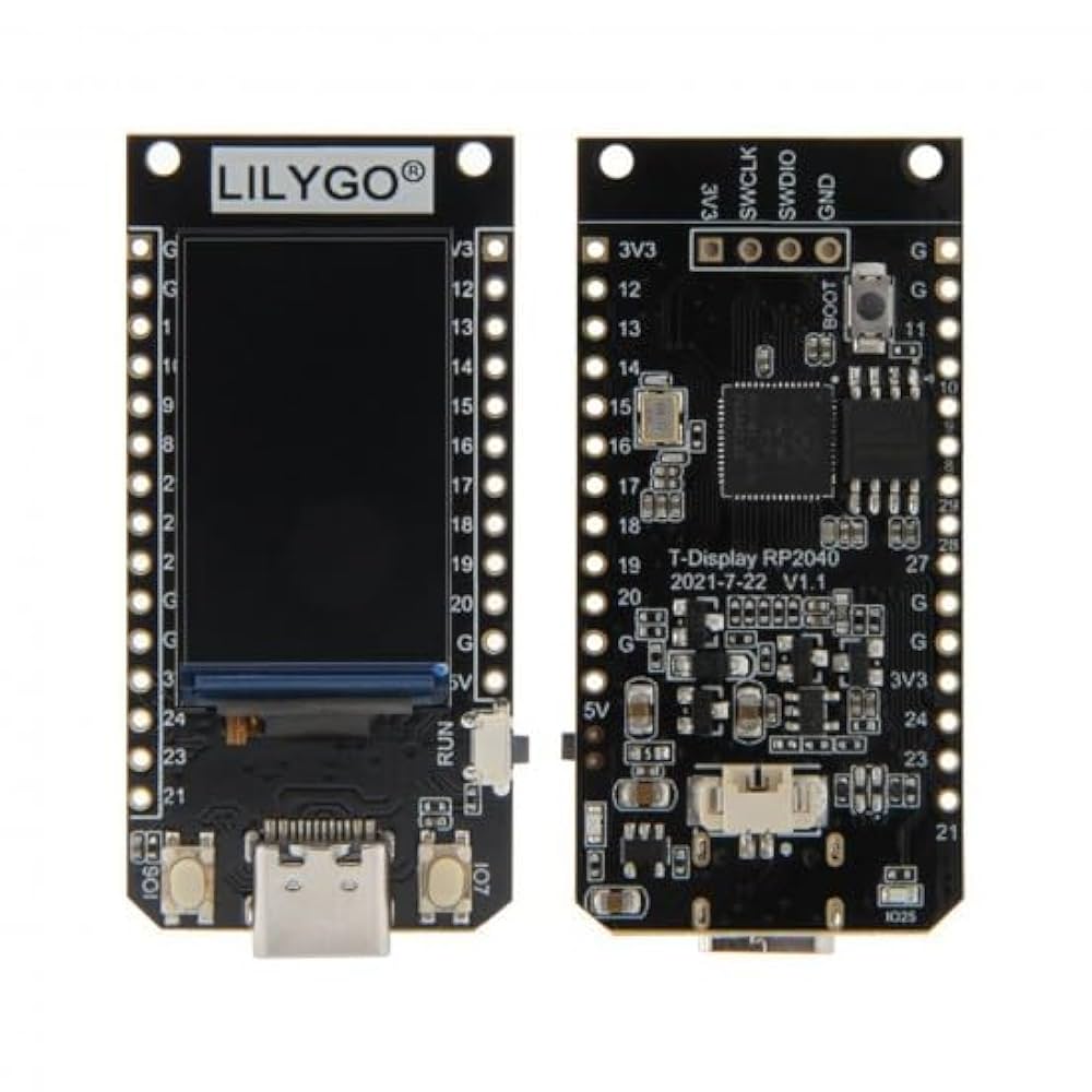
LILYGO T-Display
It Comes with built in peripherals like OLED displays, cameras, GPS, or LoRa. Main microcontroller of these boards are ESP32 and its series.
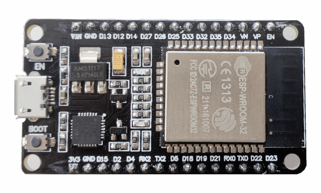
ESP32 Development Board
Here the ESP32 refers the Microcontroller. Dev boards comes with different name and different pin size. Even though the operations are same, some pin level function may change depends on the boards. Here we use ESP32 DevKit V1 as reference ESP32 Dev board (depends on the manufacturer it may termed as ESP32 DevKit DOIT). All you need to see on the board is ‘ESP32‘ and its pinout before start to code.
ESP32 DOIT Devkit V1 Pinout
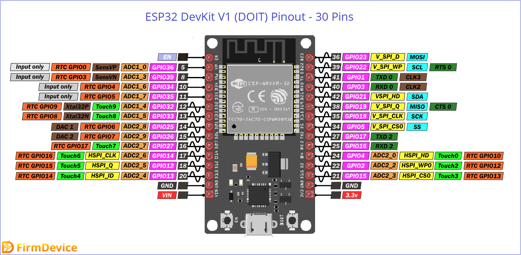
As you can see four power pins, one EN (enable) pin and then 25 GPIO pins, here GPIO pins are multifunctional and their functions also mentioned. Keep in mind that these GPIO pins handle only 3.3V so don’t apply or expect 5V. Use 3.3V to 5V logic converter if you need 5V output.
IDE for ESP32 Boards
All ESP32 boards are supported by a wide range of development tools and IDEs. Here is a list of the top IDEs.
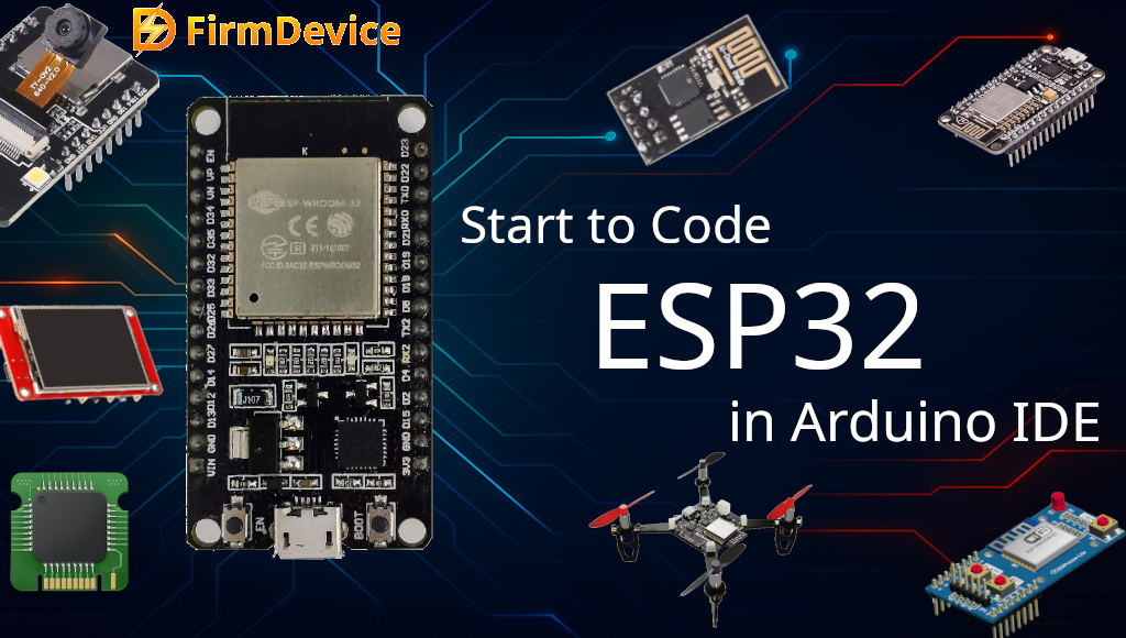
- Arduino IDE : It is beginner friendly, uses simplified codes, and it requires ESP32 Core Installation.
- ESP-IDF : Espressif IoT Development Framework, this is the official framework from Espressif, suitable for advanced users and developers.
- PlatformIO : This is the IDE solution for Visual studio Code. It supports multiple platforms and have rich environment with libraries, debugging tools, and more. You can install it as extension in VS code.
Getting Started to Code ESP32 Board
Here is the easy to follow simple steps to getting started to code ESP32 Board using Arduino IDE.
Hope you have Arduino IDE installed on you computer and have ESP32 DOIT Devkit V1 board on you hand.
Step 1: Connect the ESP32 board to Computer using MicroUSB cable.
Step 2: Some computer may install USB driver automatically, if your board USB port not recognized by your computer then Install CP210x or CH340 drivers if your board uses them for USB-to-Serial.
Step 3: Install ESP32 Core in Arduino IDE, by clicking Preferences > Additional Board Manager URLs, and then add: “https://raw.githubusercontent.com/espressif/arduino-esp32/gh-pages/package_esp32_index.json” – this address and then install from Boards Manager.
Step 4: Select the Board and Connected port – here board is DOIT ESP32 DEVKIT V1, Choose your ESP32 model from the Tools > Board menu and select the correct COM port.
Step 5: Test it with the following Blink code, by uploading.
// ESP32 Onboard LED Blink Example

// Define the onboard LED pin (usually GPIO 2 on most ESP32 boards)
#define LED_BUILTIN 2

void setup() {
  pinMode(LED_BUILTIN, OUTPUT);  // Set the LED pin as output
}

void loop() {
  digitalWrite(LED_BUILTIN, HIGH);   // Turn the LED on
  delay(1000);                       // Wait for 1 second
  digitalWrite(LED_BUILTIN, LOW);    // Turn the LED off
  delay(1000);                       // Wait for 1 second
}
Output
Comments (0)
Log in to leave a comment.
No comments yet. Be the first!