ESP32 GPIO Examples
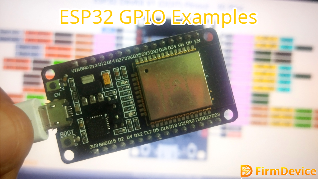
ESP32 Microcontroller form Espressif systems provides wide range of I/O functionalities. It comes in 48 pin QFN package, these pins other than bias and system pins can be configured for different purposes based on the requirement. Either we should use PCB or Module to implement ESP32 chip in a application. ESP32 SoC contains dual core processor, Wi-Fi, Bluetooth radio communication blocks.
Introduction to GPIO
GPIO means General Purpose Input / Output, these pins are configurable digital pins that can be programmed as either,
- Input – To receive signals from external sources like sensors, buttons..,
- Output – To send control signals to devices such as LEDs, Relay or output actuators..,
Here in ESP32 microcontroller and development board GPIO pins not only used for Input and Output functions, they can be used for ADC, DAC, PWM, Capacitive touch sensing, Interrupts, timer and serial communication interfaces etc.,
ESP32 GPIO Pins
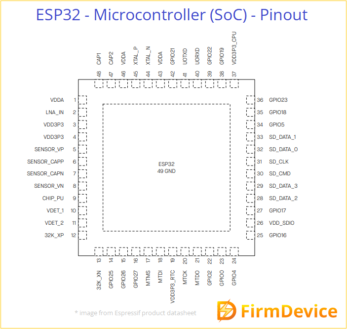
ESP32 Microcontroller chip have 36 GPIO pins but depends on the module and development board variant these count may vary, not all are available for user applications due to internal usage, the following capabilities are typically supported.
- Most pins support digital input and output.
- 18 channels ADC with 12-bit resolution.
- 2 channels DAC available on GPIO25 and GPIO26.
- Any GPIO can generate PWM signals.
- 10 GPIOs with Capacitive touch sensing capability.
- Communication protocol support for UART, SPI, and I²C on configurable pins.
Pin Multiplexing feature makes it possible to have multifunction in single pin.
WROOM32 GPIO Pins
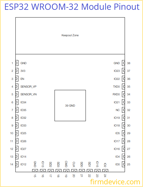
WROOM 32 is a module encapsulated with metal that contains PCB with Antenna track for WiFi, external flash memory chip and ESP32 SoC all soldered together to get the full feature of ESP32 microcontroller. It will have 38 pins, many pins acts as multifunctional pins. You can use this WROOM 32 module to make your own custom ESP32 development board.
ESP32 Devkit V1 Development Board Pinout
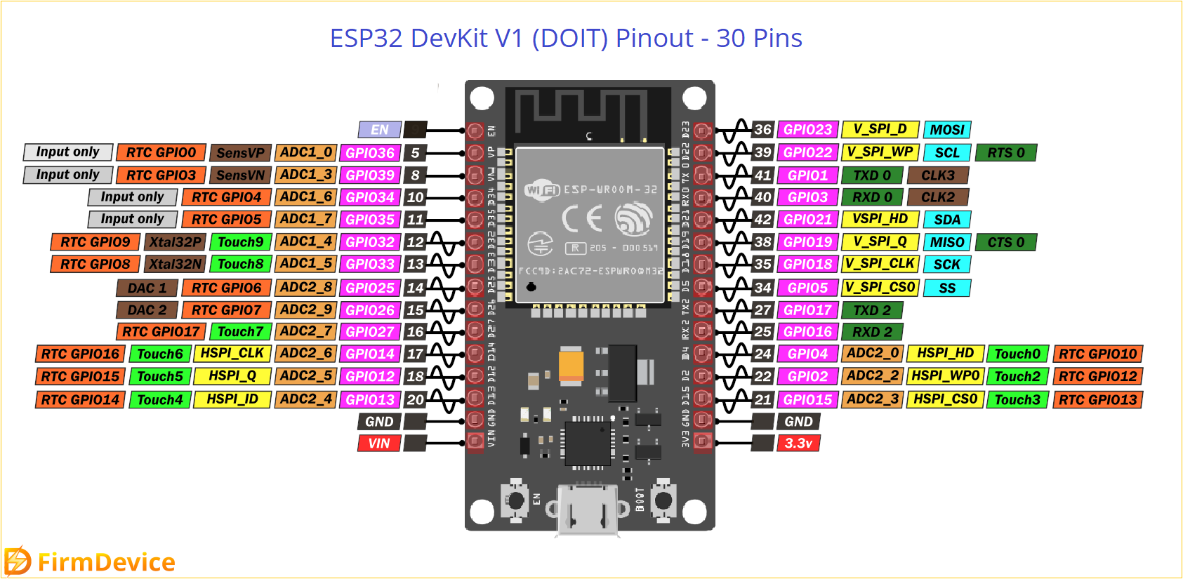
ESP32 GPIO examples are brought to you from most famous ESP32 Devkit V1 DOIT board. Remember ESP32 comes in different development boards and with different count pinouts, but same pins of development boards works same, there is no difference. You may see count of pins vary depends on boards but the GPIO pin numbers will be same for all type of development boards.
GPIO – General Purpose Input / Output pins in the microcontroller serve as the primary interface for external peripherals, sensors and output actuators. Lets see detailed overview of GPIO functions and examples.
Look at the General Pinout details of ESP32 Devkit V1 DOIT version. This board have 30 Pins. Each pin will do multifunction depends on the code, other than bias pins.
ESP32 Devkit V1 GPIO pins

This development board have 25 GPIO pins, by programming the Registers of these pins we can manage to assign different functions.
Safe to use GPIO pins are, GPIO 4, 13, 14, 16, 17, 18, 19, 21, 22, 23, 25, 26, 27, 32, 33. Here GPIO 2 is attached with on board LED and other pins have unique functions so its better to avoid those to use in specific need.
Input only GPIO pins are, GPIO 34, 35, 36 (VP), 39 (VN) these are cannot be programmed as output pins.
Pins to Avoid that is allocated for Reserved and Special use, Flash related pins GPIO 6, 7, 8, 9, 10, 11. Bootstrapping pins GPIO 0, GPIO 2, GPIO 12, GPIO 15.
GPIO Analog Read Example of ESP32
Use potentiometer and read the analog voltage value from it with ESP32.
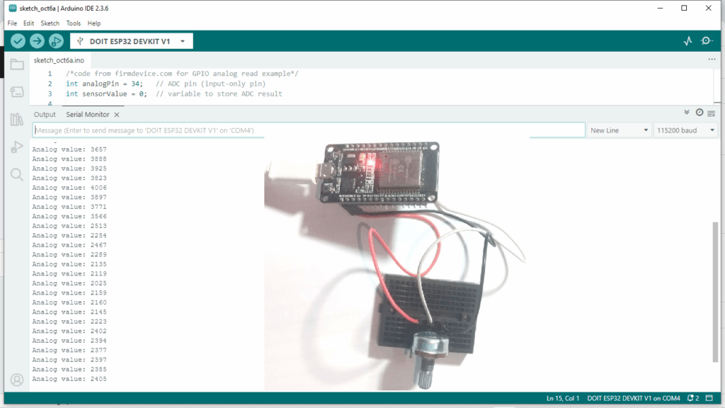
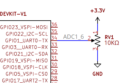 Connect +3.3V to the potentiometer terminal 1 (either way) and connect GND to terminal 3 then connect wiper Output pin to GPIO34 which is input only ADC1_6 pin of ESP32 then upload the following code and observe the output in serial monitor of arduino ide.
/*code from firmdevice.com for GPIO analog read example*/
int analogPin = 34;   // ADC pin (input-only pin)
int sensorValue = 0;  // variable to store ADC result

void setup() {
  Serial.begin(115200);  // Start serial communication
}

void loop() {
  sensorValue = analogRead(analogPin);  // Read analog value (0 - 4095)
  Serial.print("Analog value: ");
  Serial.println(sensorValue);
  delay(500);  // Wait half a second
} 
GPIO Analog Write Example of ESP32
In ESP32 Devkit V1 development board only GPIO25 and GPIO26 will support DAC, so that here we write a code and make the ESP32 convert digital value to Analog voltage signal and read it through multimeter.
Just connect multimeter in GPIO25 and GND pin of ESP32 and read the voltage.
/*code from firmdevice.com for GPIO analog write example*/
int dacPin = 25;  // DAC1 (GPIO25) or DAC2 (GPIO26)

void setup() {
}

void loop() {
  // Sweep output from 0 to 255
  for (int val = 0; val <= 255; val++) {
    dacWrite(dacPin, val);  // Write analog value (0-255)
    delay(10);
  }

  // Sweep back from 255 to 0
  for (int val = 255; val >= 0; val--) {
    dacWrite(dacPin, val);
    delay(10);
  }
}
Getting analog voltage output from GPIO25 pin of ESP32.
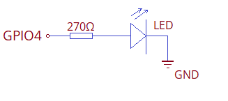
GPIO Digital Write Example of ESP32
Connect an LED Anode pin to GPIO4 pin through 270Ω Resistor then connect LED cathode pin to GND of ESP32 board then upload the following code to experiment digital write. Here Logic HIGH is 3.3V max and Logic LOW is 0V.
/*code from firmdevice.com for Digital Write Example with ESP32*/
int ledPin = 4;  // onboard LED or external LED connected to GPIO2

void setup() {
  pinMode(ledPin, OUTPUT);  // configure GPIO as output
}

void loop() {
  digitalWrite(ledPin, HIGH);  // turn LED ON
  delay(1000);                 // wait 1 second
  digitalWrite(ledPin, LOW);   // turn LED OFF
  delay(1000);                 // wait 1 second
}
And examples goes one, remember to use pull up and pull down resistor in the GPIO pins while you are working with Digital input and output.

Comments (0)
Log in to leave a comment.
No comments yet. Be the first!