ESP32 Deep Sleep Mode Guide for Power Saving
Power Efficiency is Important for battery powered device and IoT applications. ESP32 from Espressif delivers very good deep sleep modes. It allows the ESP32 Microcontroller chip to consume as little as 10 μA of current while staying ready to wakeup on demand and also retaining critical information. Let’s learn about
- What is Deep Sleep Mode & Why we need it?
- Types of ESP32 Sleep Mode.
- Types of Wakeup Sources.
- How the ESP32 Sleep Mode Works?
What is Deep Sleep Mode & Why we need it?
ESP32 Deep Sleep mode is a low power state where the main CPU core, memory, wifi and Bluetooth are all powered down. However certain components remain active depends on the sleep mode. They are,
- RTC Memory – Real Time Clock memory
- RTC Peripherals – For to allow Wake up triggers from GPIOs
- ULP Co-processor – To monitor sensor or GPIO.
We need deep sleep modes in microcontrollers to save power especially in Battery powered and Energy Efficient devices. Few examples are,
- Smart Agriculture Sensors.
- Remote environment sensors.
- Wearable devices.
- Remote transceivers.
Types of ESP32 Sleep Mode & Power Consumption
| ESP32 Operation Mode | Current Draw-Approximate Value |
|---|---|
| Active (All ON) | 150 to 240 mA |
| Modem Sleep | 3 to 20 mA |
| Light Sleep | 0.8 to 2.5 mA |
| Deep Sleep | 10 to 150 µA |
| Hiberneation | 5 µA |
Types of Wake Up Sources
ESP32 Microcontroller supports the following wake up sources from Deep Sleep and other Sleep modes.
| Source | Description |
|---|---|
| Timer | Wake up after a set duration |
| Touch Pad | Capacitive touch sensor detection |
| External GPIO | Any configured GPIO pin (high/low level trigger) |
| ULP Co-processor | Programmed logic or sensor monitoring |
You can code ESP32 to use multiple wake up sources, to get wake up from sleep mode.
How the ESP32 Sleep Mode Works?
ESP32 Microcontroller Have multiple blocks inside the Architecture, during the sleep mode specific or whole blocks goes to sleep and reduce their power consumptions except some wake up sources.
Active Mode
Active Mode is the normal operation mode of ESP32 Microcontroller. Here all the Architectural blocks are active and working. So that current and power consumption will be higher than all other modes that is up to 240 mA some times more than that.
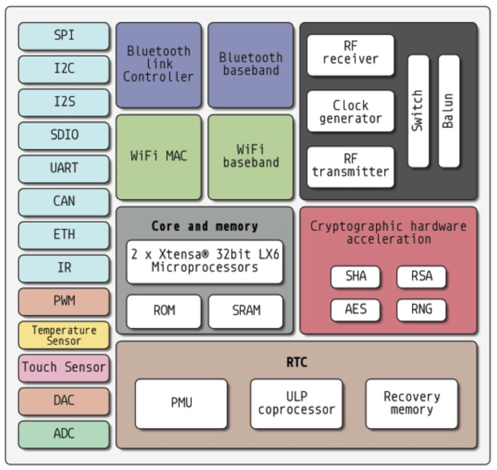
| ESP32 Architecture Block | Operation Status |
| Peripherals | ON |
| Bluetooth | ON |
| WiFi | ON |
| Radio | ON |
| ESP32 Core | ON |
| ULP CoProcessor | ON |
| RTC | ON |
Hope this simple table helps you to understand operations status of internal blocks.
Modem Sleep
In Modem Sleep, ESP32 Microcontroller makes every blocks active except WiFi, Bluetooth and Radio blocks. In this mode it consumes current between 3 mA to 20 mA.
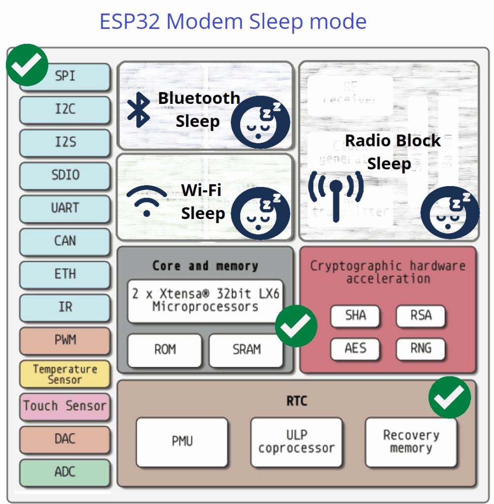
| ESP32 Architecture Block | Operation Status |
| Peripherals | ON |
| Bluetooth | OFF |
| WiFi | OFF |
| Radio | OFF |
| ESP32 Core | ON |
| ULP CoProcessor | ON |
| RTC | ON |
If you are in need to have wireless communication during Modem Sleep mode, you can make ESP32 to switch to active mode for predefined intervals. So that Wifi block works between DTIM beacon intervals.
Light Sleep Mode
ESP32 Light Sleep Mode puts the CPU Core in periodical off and most clocks to save power but keeps memory, RTC and ULP in on condition. In this mode ESP32 wakes up faster than deep sleep mode by using timer or GPIO interrupt input. In this mode ESP32 consumes 0.8 to 2.5 mA current for its operation.
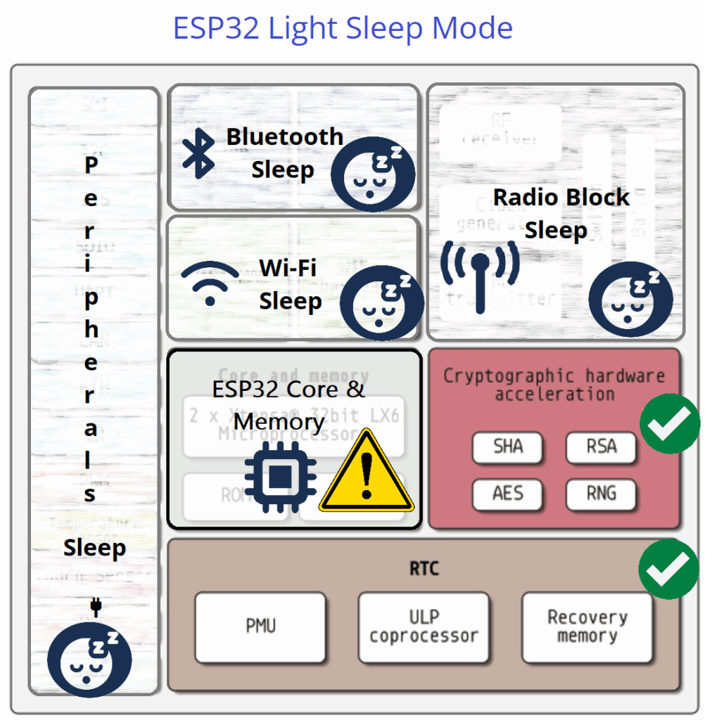
| ESP32 Architecture Block | Operation Status |
| Peripherals | OFF |
| Bluetooth | OFF |
| WiFi | OFF |
| Radio | OFF |
| ESP32 Core | Periodic ON/OFF |
| ULP CoProcessor | ON |
| RTC | ON |
Deep Sleep Mode
In Deep Sleep Mode ESP32 turns off CPU core, Memory, WiFi, Bluetooth, Radio and Peripherals and keeps active few blocks which helps to wake up ESP32 Core. Due to all power consuming blocks stays in OFF condition, deep sleep mode only consumes 10 to 150 µA current for its operation.
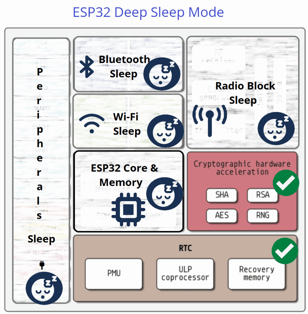
Here ULP CoProcessor, RTC Peripherals, RTC Controller and RTC memory (Fast & Slow) only stays active.
| ESP32 Architecture Block | Operation Status |
| Peripherals | OFF |
| Bluetooth | OFF |
| WiFi | OFF |
| Radio | OFF |
| ESP32 Core | OFF |
| ULP CoProcessor | ON |
| RTC | ON |
Hiberneation Mode
Hibernation mode in ESP32 is the Lowest Power State here everything is powered down except RTC memory and RTC timer. In this mode RTC timer and External GPIO wake up source only stays ON. So the ESP32 Core wakes up by these two blocks and it performs a cold boot like power on reset and so all the blocks comes to alive. In this mode ESP32 consume only 5 μA.
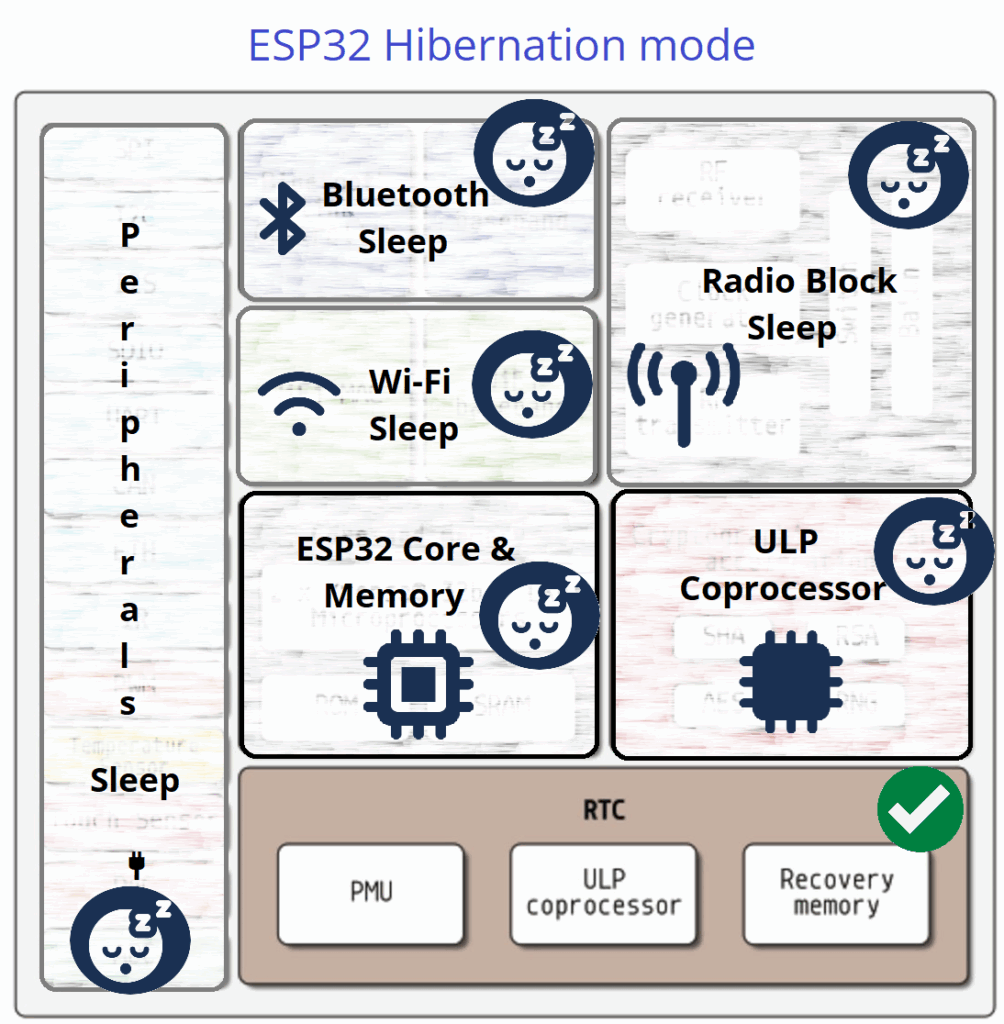
| ESP32 Architecture Block | Operation Status |
| Peripherals | OFF |
| Bluetooth | OFF |
| WiFi | OFF |
| Radio | OFF |
| ESP32 Core | OFF |
| ULP CoProcessor | OFF |
| RTC | ON |
Deep Sleep Mode and Wake up Examples
Deep Sleep Mode in ESP32 is the best to choose from all sleep modes available, because it saves maximum power and also keep some data then resume quickly when gets wake up. In this mode RTC, ULP Co Processor stays ON so that we can use timer, GPIO, touch pad and ULP to wake up ESP32 microcontroller from deep sleep.
One thing you have to remember that in Deep Sleep mode ESP32 CPU core and Memory Pushed to turn OFF so that ESP32 Wakes up with Reset. Hence the Code execution starts from beginning on every wake up. So that we have to setup the Wake Up source before the Deep Sleep code starts “esp_deep_sleep_start( )” when you look at the example code you can easily understand.
We know that Main memory is erased during Deep Sleep mode because it is pushed to turn OFF so that we need another place to store the data, for Deep Sleep mode we can use RTC memory because it stays ON during that mode. By using “RTC_DATA_ATTR int bootCount= 0;” this code makes RTC memory to be accessed globally during wake up from deep sleep.
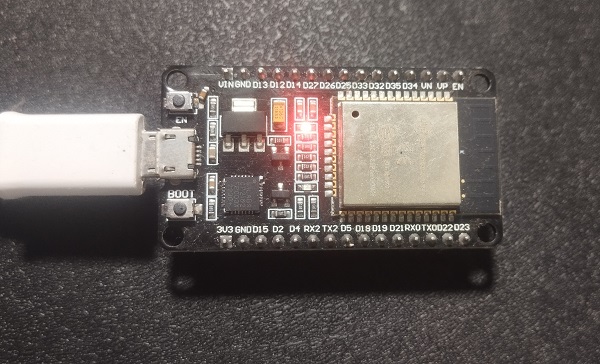
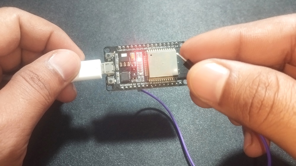
Following Example codes are tested with ESP32 DOIT Dev Kit V1 board and Arduino IDE.
Deep Sleep with Timer Wake up Code
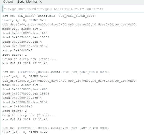
Here is the simple Arduino Code to exhibit Deep Sleep with Timer Wake up. RTC timer from the RTC block is used here to monitor the time duration and gives wake up signal to ESP32 Core. Here time is in microseconds for RTC and using the function “esp_sleep_enable_timer_wakeup(TIME_TO_SLEEP * uS_TO_S_FACTOR);“. Following example code puts ESP32 in deep sleep for 5 seconds then wakes up using timer block. Meanwhile data stored in RTC memory and gets printed.
/* Deep Sleep with Timer Wake up Code from firmdevice.com */
#define uS_TO_S_FACTOR 1000000ULL  // Conversion factor for micro seconds to seconds
#define TIME_TO_SLEEP 5          // Time ESP32 will sleep (in seconds)

RTC_DATA_ATTR int bootCount = 0;

void setup() {
  Serial.begin(115200);
  delay(1000);

  bootCount++;
  Serial.printf("Boot count: %d\n", bootCount);

  esp_sleep_enable_timer_wakeup(TIME_TO_SLEEP * uS_TO_S_FACTOR);
  Serial.println("Going to sleep now (Timer)...");

  esp_deep_sleep_start();
}

void loop() {
  // not used
}
Output in Serial Monitor
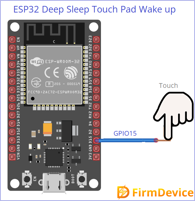
Deep Sleep with Touch Pad (pin) Wake up Code
In Touch to Wake up method we can bring ESP32 to alive from deep sleep by mentioning Touch pad pin in the code. During Deep Sleep RTC and Connected Touch Sensor Hardware pin stays ON so that we can use those pins to wake up ESP32. Here you have to give external trigger by touching pad or pin connected to the mentioned (in code) pin of ESP32 chip. The following pins only support external touch input.
Touch Pad T0–T9 (GPIO 4, 0, 2, 15, 13, 12, 14, 27, 33, 32), Check the data sheet of ESP32 Development board before jump in to code because there are different pin size development board roaming.
| Touch Pad | GPIO Number |
|---|---|
| T0 | GPIO 4 |
| T1 | GPIO 0 |
| T2 | GPIO 2 |
| T3 | GPIO 15 |
| T4 | GPIO 13 |
| T5 | GPIO 12 |
| T6 | GPIO 14 |
| T7 | GPIO 27 |
| T8 | GPIO 33 |
| T9 | GPIO 32 |
Wiring Diagram
Important function to Setup Touch Wake up
Use touchAttachInterrupt( ) to configure a touch threshold.
Enable touch wake up using esp_sleep_enable_touchpad_wakeup( )
Start deep sleep with esp_deep_sleep_start( )
/* Deep Sleep with Touch pad Wake up Code from firmdevice.com */
#include "esp_sleep.h"
#include "driver/touch_pad.h"

void touchWakeStub() {
  // Empty function – required by touchAttachInterrupt
}

void setup() {
  Serial.begin(115200);
  delay(1000);
  Serial.println("Woke up from deep sleep by Touch!");

  // Your action code here
  delay(3000); // Simulate some work

  // Setup touch threshold and interrupt
  touchAttachInterrupt(T0, touchWakeStub, 40);  // T0 = GPIO4

  // Enable touch wake-up
  esp_sleep_enable_touchpad_wakeup();

  Serial.println("Going to Deep Sleep. Touch GPIO4 (T0) to wake up.");
  esp_deep_sleep_start();  // Enter deep sleep
}

void loop() {
  // Nothing here – ESP32 won't run loop() after deep sleep
}
Output in Serial Monitor
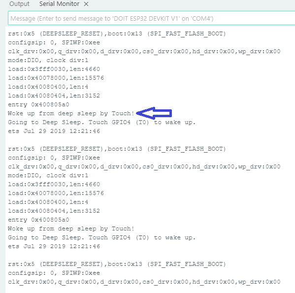
This code makes ESP32 to go deep sleep and when you touch pin (GPIO4) then ESP32 gets wake up and then wait for some time (delay) here you can put your task code and then ESP32 goes to deep sleep. This routine continue when ever you touch the pin.
Deep Sleep with External Interrupt Wake up using GPIO
ext0 and ext1 are wake up sources in ESP32 Microcontroller, these two uses RTC GPIO pins to wake up esp32 externally. ext0 wake up method uses only one pin (single pin). ext1 wake up method uses multiple pins. Both ext0 and ext1 only work with RTC GPIOs, these pins are stay alive during deep sleep.
RTC GPIOs ESP32: 0, 2, 4, 12–15, 25–27, 32–39
| ext0 | ext1 | |
|---|---|---|
| Pins Supported | Only 1 | Multiple |
| Trigger Type | Edge (LOW) | Level (ANY_HIGH / ALL_LOW) |
| Use Case | Simple button/sensor | Multiple inputs / conditions |
- If you are feeding one input like button or sensor then you can use ext0 to wake up from deep sleep.
- If you are feeding more than one input then use ext1 to wake up ESP32 from deep sleep.
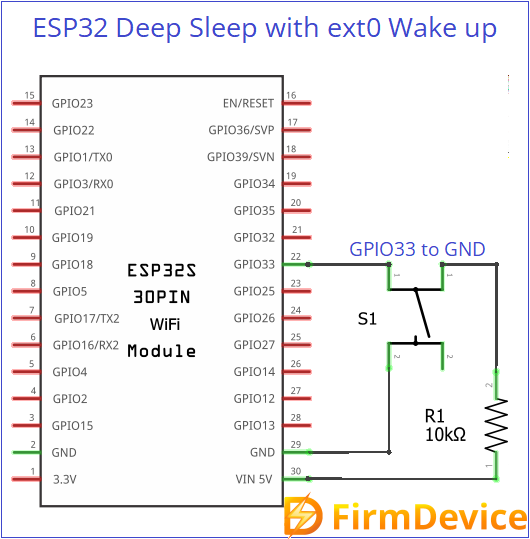
Deep Sleep with ext0 Wake up
Use this function esp_sleep_enable_ext0_wakeup(WAKEUP_PIN, 0);
Deep Sleep with ext0 Wake up Circuit
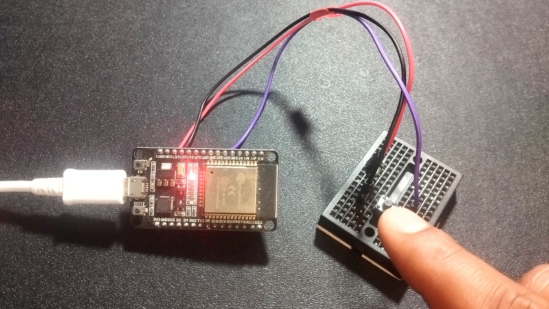
Connect a push button switch between GPIO33 pin and GND. When we press the button, ESP32 gets wake up from deep sleep.
/* Deep Sleep with ext0 Wake up Code from firmdevice.com */
#define WAKEUP_PIN GPIO_NUM_33  // Must be RTC GPIO
RTC_DATA_ATTR int bootCount = 0;

void setup() {
  Serial.begin(115200);
  delay(1000);

  bootCount++;
  Serial.printf("Boot Count: %d\n", bootCount);

  esp_sleep_wakeup_cause_t cause = esp_sleep_get_wakeup_cause();
  if (cause == ESP_SLEEP_WAKEUP_EXT0) {
    Serial.println("Wake-up from EXT0 (falling edge on one GPIO)");
  }

  // Setup ext0 wake-up
  pinMode(WAKEUP_PIN, INPUT_PULLUP);  // Button pulls LOW
  esp_sleep_enable_ext0_wakeup(WAKEUP_PIN, 0);  // Wake on LOW

  Serial.println("Entering deep sleep. Press button to wake.");
  delay(2000);
  esp_deep_sleep_start();
}

void loop() {
  // Nothing here
}
Testing ext0
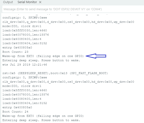
Output in Serial Monitor
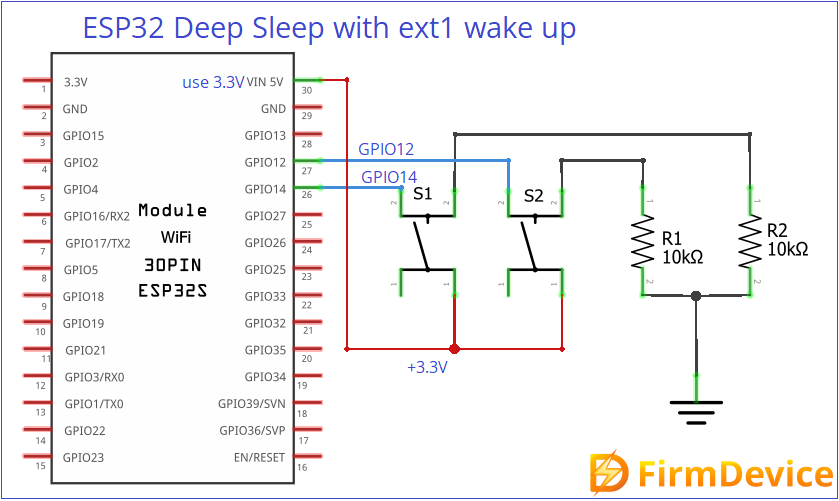
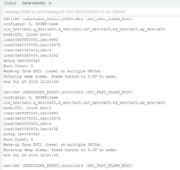
Deep Sleep with ext1 Wake up
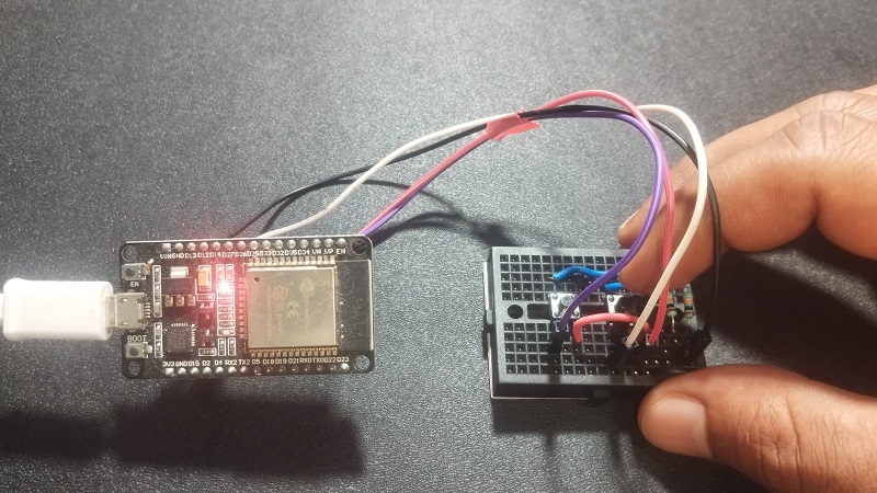
Here we can use multiple GPIOs to wake up ESP32 from Deep Sleep as previously said those GPIOs must be RTC pins. Just connect GPIO12 and GPIO14 to 3.3V using two push buttons. Upload the following code to test it.
/* Deep Sleep with ext1 Wake up Code from firmdevice.com */
#define WAKEUP_PIN_1 GPIO_NUM_12
#define WAKEUP_PIN_2 GPIO_NUM_14

RTC_DATA_ATTR int bootCount = 0;

void setup() {
  Serial.begin(115200);
  delay(1000);

  bootCount++;
  Serial.printf("Boot Count: %d\n", bootCount);

  esp_sleep_wakeup_cause_t cause = esp_sleep_get_wakeup_cause();
  if (cause == ESP_SLEEP_WAKEUP_EXT1) {
    Serial.println("Wake-up from EXT1 (level on multiple GPIOs)");
  }

  // Setup ext1 wake-up (wake if ANY pin is HIGH)
  pinMode(WAKEUP_PIN_1, INPUT);
  pinMode(WAKEUP_PIN_2, INPUT);
  esp_sleep_enable_ext1_wakeup(
    BIT64(WAKEUP_PIN_1) | BIT64(WAKEUP_PIN_2),
    ESP_EXT1_WAKEUP_ANY_HIGH
  );

  Serial.println("Entering deep sleep. Press button to 3.3V to wake.");
  delay(2000);
  esp_deep_sleep_start();
}

void loop() {
  // Nothing here
}
Testing ext1
Output in Serial Monitor
ESP32 Deep Sleep with ULP CoProcessor Wake up
Here the ULP represents Ultra Low Power, ULP coprocessor lets ESP32 to run small tasks like reading ADC value, GPIO check etc., even during deep sleep. It can wake up the main ESP32 CPU core only if needed that should be mentioned in code, this will save battery power. You may need ESP-IDF or ULP macros in IDE to writ ULP coprocessor wake up in ESP32. That is separate topic to be see.
In Short
ESP32 Microcontroller can be put into deep sleep mode and then make it wake up using Timer, Touch Pad (pin), External GPIOs (ext0, ext1) and then ULP. When you are applying external power supply to ESP32 remember to apply only 3.3V, excess voltage may damage the chip.
Comments (0)
Log in to leave a comment.
No comments yet. Be the first!